Chapter 2 - The Programmable Logic Controller
2-1. Objectives 目标
Upon completion of this chapter you will know
读完这一章,你就会知道。
²
the history of
the programmable logic controller.
²
回顾了可编程逻辑控制器的历史。
²
why the first
PLCs were developed and why they were better than the existing control methods.
²
为什么开发了第一批PLC,为什么它们比现有的控制方法更好。
²
the difference
between the open frame, shoebox, and modular PLC configurations, and the
advantages and disadvantages of each.
²
开放式框架、鞋盒和模块化可编程控制器配置之间的区别,以及每种配置的优缺点。
²
the components
that make up a typical PLC.
²
构成典型可编程控制器的组件。
²
how programs are
stored in a PLC.
²
程序在可编程控制器中的存储方式。
²
the equipment
used to program a PLC.
²
可编程控制器()用来对可编程控制器进行编程的设备。
²
the way that a
PLC inputs data, outputs data, and executes its program.
²
可编程控制器输入数据、输出数据和执行其程序的方式。
²
the purpose of
the PLC update.
²
是可编程控制器更新的目的。
²
the order in
which a PLC executes a ladder program.
²
执行阶梯程序的顺序。
²
how to calculate
the scan rate of a PLC.
²
如何计算可编程控制器的扫描速率。
2-2. Introduction 介绍
This chapter will introduce the
programmable logic controller (PLC) with a brief discussion of it's history and
development, and a study of how the PLC executes a program.
本章将介绍可编程控制器(PLC),简要讨论它的历史和发展,并研究PLC是如何执行程序的。
A physical description of the various configurations of programmable logic
controllers, the functions associated with the different components, will
follow.
下面将对可编程逻辑控制器的各种配置、与不同组件相关联的功能进行物理描述。
The chapter will end with a discussion of the unique way that a programmable
logic controller obtains input data, process it, and produces output data,
including a short introduction to ladder logic.
本章最后将讨论可编程逻辑控制器获取输入数据、处理数据和产生输出数据的独特方式,包括对梯形逻辑的简短介绍。
It should be noted that in usage, a programmable logic controller is generally
referred to as a “PLC” or “programmable controller”.
应当注意,在使用中,可编程逻辑控制器通常被称为“PLC”或“可编程控制器”。
Although the term “programmable controller” is generally
accepted, it is not abbreviated “PC” because the abbreviation “PC” is usually used in reference to a personal computer.
虽然术语“可编程控制器”被普遍接受,但它并不缩写为“PC”,因为缩写“PC”通常用于指个人计算机。
As we will see in this chapter, a PLC is by no means a personal computer.
正如我们将在本章中看到的,PLC绝不是个人计算机。
2-3. A Brief History 简要历史
Early machines were controlled by
mechanical means using cams, gears, levers and other basic mechanical devices.
早期的机器是由机械手段控制的,使用凸轮、齿轮、杠杆和其他基本的机械装置。
As the complexity grew, so did the need for a more sophisticated control
system.
随着复杂性的增加,对更复杂的控制系统的需求也在增加。
This system contained wired relay and switch control elements.
该系统包括有线继电器和开关控制元件。
These elements were wired as required to provide the control logic necessary
for the particular type of machine operation.
这些元件根据需要进行布线,以提供特定类型的机器操作所需的控制逻辑。
This was acceptable for a machine that never needed to be changed or modified,
but as manufacturing techniques improved and plant changeover to new products
became more desirable and necessary, a more versatile means of controlling this
equipment had to be developed.
对于一台从不需要更换或修改的机器来说,这是可以接受的,但随着制造技术的改进和工厂向新产品的转换变得更加可取和必要,必须开发一种更通用的方法来控制这种设备。
Hardwired relay and switch logic was cumbersome and time consuming to modify.
硬连线的继电器和开关逻辑修改起来既麻烦又耗时。
Wiring had to be removed and replaced to provide for the new control scheme
required.
必须拆除和更换布线,以提供所需的新控制方案。
This modification was difficult and time consuming to design and install and
any small "bug" in the design could be a major problem to correct
since that also required rewiring of the system.
这种修改设计和安装既困难又耗时,而且设计中的任何小“错误”都可能是需要纠正的大问题,因为这也需要重新布线系统。
A new means to modify control circuitry was needed.
需要一种新的方法来修改控制电路。
The development and testing ground for this new means was the U.S. auto
industry.
这一新手段的开发和试验场是美国汽车业。
The time period was the late 1960's and early 1970's and the result was the
programmable logic controller, or PLC.
这段时间是20世纪60年代末和70年代初,结果就是可编程逻辑控制器(PLC)。
Automotive plants were confronted with a change in manufacturing techniques
every time a model changed and, in some cases, for changes on the same model if
improvements had to be made during the model year.
每当车型改变时,汽车工厂都会面临制造技术的变化,在某些情况下,如果必须在车型年内进行改进,还会对同一车型进行改变。
The PLC provided an easy way to reprogram the wiring rather than actually
rewiring the control system.
PLC提供了一种重新编程布线的简单方法,而不是实际重新布线控制系统。
The PLC that was developed during this time was not very easy to program.
在此期间开发的PLC并不是很容易编程。
The language was cumbersome to write and required highly trained programmers.
这种语言编写起来很麻烦,而且需要训练有素的程序员。
These early devices were merely relay replacements and could do very little
else.
这些早期的设备仅仅是继电器的替代品,几乎不能做其他的事情。
The PLC has at first gradually, and in recent years rapidly developed into a
sophisticated and highly versatile control system component.
PLC最初是逐渐发展起来的,最近几年迅速发展成为一种成熟的、通用性很强的控制系统部件。
Units today are capable of performing complex math functions including
numerical integration and differentiation and operate at the fast
microprocessor speeds now available.
今天的单元能够执行复杂的数学功能,包括数值积分和微分,并以目前可用的快速微处理器速度运行。
Older PLCs were capable of only handling discrete inputs and outputs (that is,
on-off type signals), while today's systems can accept and generate analog
voltages and currents as well as a wide range of voltage levels and pulsed
signals.
较早的PLC只能处理离散的输入和输出(即开关类型的信号),而今天的系统可以接受和产生模拟电压和电流,以及大范围的电压电平和脉冲信号。
PLCs are also designed to be rugged.
PLC也是设计成坚固耐用的。
Unlike their personal computer cousin, they can typically withstand vibration,
shock, elevated temperatures, and electrical noise to which manufacturing
equipment is exposed.
与他们的个人电脑表亲不同,他们通常可以承受制造设备暴露在其中的振动、冲击、高温和电气噪音。
As more manufacturers become involved in PLC production and development, and
PLC capabilities expand, the programming language is also expanding.
随着越来越多的制造商参与PLC的生产和开发,以及PLC功能的扩展,编程语言也在不断扩展。
This is necessary to allow the programming of these advanced capabilities.
这是允许编程这些高级功能所必需的。
Also, manufacturers tend to develop their own versions of ladder logic language
(the language used to program PLCs).
此外,制造商倾向于开发他们自己版本的梯形逻辑语言(用于编程PLC的语言)。
This complicates learning to program PLC's in general since one language cannot
be learned that is applicable to all types.
这通常会使学习PLC编程变得复杂,因为不可能学习一种适用于所有类型的语言。
However, as with other computer languages, once the basics of PLC operation and
programming in ladder logic are learned, adapting to the various manufacturers’ devices is not a complicated process.
然而,与其他计算机语言一样,一旦学习了PLC操作和梯形逻辑编程的基础知识,适应各种制造商的设备并不是一个复杂的过程。
Most system designers eventually settle on one particular manufacturer that
produces a PLC that is personally comfortable to program and has the
capabilities suited to his or her area of applications.
大多数系统设计人员最终选择了一家特定的制造商,该制造商生产的PLC个人编程舒适,并且具有适合其应用领域的功能。
2-4. PLC Configurations 配置
Programmable controllers (the
shortened name used for programmable logic controllers) are much like personal
computers in that the user can be overwhelmed by the vast array of options and
configurations available.
可编程控制器(可编程逻辑控制器的缩写)与个人计算机非常相似,因为用户可能会被大量可用的选项和配置搞得不知所措。
Also, like personal computers, the best teacher of which one to select is
experience.
而且,和个人电脑一样,最好的老师是经验。
As one gains experience with the various options and configurations available,
it becomes less confusing to be able to select the unit that will best perform
in a particular application.
随着人们获得各种可用选项和配置的经验,能够选择在特定应用中性能最佳的设备就不那么令人困惑了。
Basic PLCs are available on a single printed circuit board as shown in Figure
2-1.
基本PLC位于单个印刷电路板上,如图2-1所示。
They are sometimes called single board PLCs or open frame PLCs.
它们有时被称为单板PLC或开放式框架PLC。
These are totally self contained (with the exception of a power supply) and,
when installed in a system, they are simply mounted inside a controls cabinet
on threaded standoffs.
它们是完全独立的(电源除外),当安装在系统中时,它们简单地安装在螺纹支架上的控制柜内。
Screw terminals on the printed circuit board allow for the connection of the
input, output, and power supply wires.
印刷电路板上的螺丝端子允许连接输入、输出和电源线。
These units are generally not expandable, meaning that extra inputs, outputs,
and memory cannot be added to the basic unit.
这些单元通常是不可扩展的,这意味着不能将额外的输入、输出和内存添加到基本单元。
However, some of the more sophisticated models can be linked by cable to
expansion boards that can provide extra I/O.
然而,一些更复杂的型号可以通过电缆连接到可以提供额外I/O的扩展板。
Therefore, with few exceptions, when using this type of PLC, the system
designer must take care to specify a unit that has enough inputs, outputs, and
programming capability to handle both the present need of the system and any
future modifications that may be required.
因此,除极少数例外,当使用这种类型的PLC时,系统设计人员必须注意指定一个具有足够的输入、输出和编程能力的单元,以满足系统当前的需要和未来可能需要的任何修改。
Single board PLCs are very inexpensive (some less than $100), easy to program,
small, and consume little power, but, generally speaking, they do not have a
large number of inputs and outputs, and have a somewhat limited instruction
set.
单板PLC非常便宜(有些不到100美元),易于编程,体积小,功耗低,但一般来说,它们的输入和输出不是很多,指令集也有点有限。
They are best suited to small, relatively simple control applications.
它们最适合小型的、相对简单的控制应用。
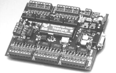
Figure 2-1 - Open Frame PLC
(Triangle Research Inc., Pte. Ltd.)
PLCs are also available housed in a
single case (sometimes referred to as a shoe box) with all input and output,
power and control connection points located on the single unit, as shown in
Figure 2-2.
PLC也可装在单个机箱(有时称为鞋盒)中,所有输入和输出、电源和控制连接点都位于单个单元上,如图2-2所示。
These are generally chosen according to available program memory and required
number and voltage of inputs and outputs to suit the application.
这些通常是根据可用的程序存储器以及所需的输入和输出的数量和电压来选择的,以适应应用。
These systems generally have an expansion port (an interconnection socket)
which will allow the addition of specialized units such as high speed counters
and analog input and output units or additional discrete inputs or outputs.
这些系统通常具有扩展端口(互连插座),它将允许添加专用单元,例如高速计数器和模拟输入输出单元或附加的离散输入或输出。
These expansion units are either plugged directly into the main case or
connected to it with ribbon cable or other suitable cable.
这些扩展单元或者直接插入主机箱,或者通过带状电缆或其他合适的电缆连接到主机箱。
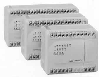
Figure 2-2 - Shoebox-Style PLCs (IDEC Corp.)
More sophisticated units, with a
wider array of options, are modularized.
更复杂的单元,有更广泛的选择,是模块化的。
An example of a modularized PLC is shown in Figure 2-3.
模块化PLC的示例如图2-3所示。
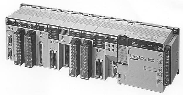
Figure 2-3 - Modularized PLC
(Omron Electronics)
The typical system components for a
modularized PLC are:
模块化PLC的典型系统组件包括:
1. Processor.
1. 处理器。
The processor (sometimes call a CPU), as in the self
contained units, is generally specified according to memory required for the
program to be implemented.
处理器(有时称为CPU),就像在自包含单元中一样,通常根据要实现的程序所需的存储器来指定。
In the modularized versions, capability can also be a
factor.
在模块化版本中,功能也可能是一个因素。
This includes features such as higher math functions, PID
control loops and optional programming commands.
这包括更高的数学函数、PID控制回路和可选的编程命令等功能。
The processor consists of the microprocessor, system
memory, serial communication ports for printer, PLC LAN link and external
programming device and, in some cases, the system power supply to power the
processor and I/O modules.
处理器由微处理器、系统存储器、打印机串行通信端口、PLC LAN链路和外部编程设备组成,在某些情况下还包括为处理器和I/O模块供电的系统电源。
2. Mounting rack.
2. 安装架。
This is usually a metal framework with a printed circuit
board backplane which provides means for mounting the PLC input/output (I/O)
modules and processor.
这通常是带有印刷电路板底板的金属框架,提供安装PLC输入/输出(I/O)模块和处理器的方法。
Mounting racks are specified according to the number of
modules required to implement the system.
根据实施系统所需的模块数量指定安装机架。
The mounting rack provides data and power connections to
the processor and modules via the backplane.
安装机架通过背板向处理器和模块提供数据和电源连接。
For CPUs that do not contain a power supply, the rack also
holds the modular power supply.
对于不包含电源的CPU,机架还可容纳模块化电源。
There are systems in which the processor is mounted
separately and connected by cable to the rack.
有些系统中的处理器是单独安装的,并通过电缆连接到机架。
The mounting rack can be available to mount directly to a
panel or can be installed in a standard 19" wide equipment cabinet.
Mounting racks are cascadable so several may be interconnected to allow a
system to accommodate a large number of I/O modules.
安装机架可以直接安装到面板上,也可以安装在标准的19英寸宽的设备机柜中。安装机架是级联的,因此可以将多个机架互连在一起,使系统能够容纳大量的I/O模块。
3. Input and output
modules.
3. 输入输出模块。
Input and output (I/O) modules are specified according to
the input and output signals associated with the particular application.
根据与特定应用相关联的输入和输出信号来指定输入和输出(I/O)模块。
These modules fall into the categories of discrete,
analog, high speed counter or register types.
这些模块分为离散、模拟、高速计数器或寄存器类型。
Discrete I/O modules are generally capable of handling 8
or 16 and, in some cases 32, on-off type inputs or outputs per module.
每个模块通常能够处理8个或16个离散I/O模块,在某些情况下可处理32个开关型输入或输出。
Modules are specified as input or output but generally not
both although some manufacturers now offer modules that can be configured with
both input and output points in the same unit.
模块被指定为输入或输出,但通常不是两者都有,尽管一些制造商现在提供可以在同一单元中同时配置输入和输出点的模块。
The module can be specified as AC only, DC only or AC/DC
along with the voltage values for which it is designed.
模块可以指定为仅交流、仅直流或AC/DC以及其设计的电压值。
Analog input and output modules are available and are
specified according to the desired resolution and voltage or current range.
模拟输入和输出模块可用,并根据所需的分辨率和电压或电流范围进行指定。
As with discrete modules, these are generally input or
output; however some manufacturers provide analog input and output in the same
module.
与分立模块一样,这些模块通常是输入或输出;但是,一些制造商在同一模块中提供模拟输入和输出。
Analog modules are also available which can directly
accept thermocouple inputs for temperature measurement and monitoring by the
PLC.
还提供模拟模块,可直接接受热电偶输入,由PLC进行温度测量和监控。
Pulsed inputs to the PLC can be accepted using a high
speed counter module.
可使用高速计数器模块接受PLC的脉冲输入。
This module can be capable of measuring the frequency of
an input signal from a tachometer or other frequency generating device.
该模块能够测量来自转速表或其他频率产生设备的输入信号的频率。
These modules can also count the incoming pulses if
desired.
如果需要,这些模块还可以对输入脉冲进行计数。
Generally, both frequency and count are available from the
same module at the same time if both are required in the application.
通常,如果应用中需要频率和计数,则可以同时从同一模块获得这两个功能。
Register input and output modules transfer 8 or 16 bit
words of information to and from the PLC.
寄存器输入和输出模块向PLC传送8位或16位字的信息,或从PLC传送8位或16位字的信息。
These words are generally numbers (BCD or Binary) which
are generated from thumbwheel switches or encoder systems for input or data to
be output to a display device by the PLC.
这些字通常是由拇指轮开关或编码器系统生成的数字(BCD或二进制),用于PLC向显示设备输入或输出数据。
Other types of modules may be available depending upon the
manufacturer of the PLC and it's capabilities.
其他类型的模块可能会根据PLC的制造商及其功能的不同而有所不同。
These include specialized communication modules to allow
for the transfer of information from one controller to another.
这些模块包括专门的通信模块,允许将信息从一个控制器传输到另一个控制器。
One new development is an I/O Module which allows the
serial transfer of information to remote I/O units that can be as far as 12,000
feet away.
一项新的开发是I/O模块,它允许将信息串行传输到最远可达12,000英尺的远程I/O单元。
4. Power supply.
4. 电源供应。
The power supply specified depends upon the manufacturer's
PLC being utilized in the application.
指定的电源取决于应用中使用的制造商的PLC。
As stated above, in some cases a power supply capable of
delivering all required power for the system is furnished as part of the
processor module.
如上所述,在某些情况下,能够为系统提供所有所需电力的电源被提供为处理器模块的一部分。
If the power supply is a separate module, it must be
capable of delivering a current greater than the sum of all the currents needed
by the other modules.
如果电源是单独的模块,则它必须能够提供大于其他模块所需所有电流总和的电流。
For systems with the power supply inside the CPU module,
there may be some modules in the system which require excessive power not
available from the processor either because of voltage or current requirements
that can only be achieved through the addition of a second power source.
对于CPU模块内有电源的系统,系统中可能有一些模块由于电压或电流要求(只能通过添加第二个电源才能实现)而需要处理器无法提供的过多电源。
This is generally true if analog or external communication
modules are present since these require ± DC supplies which, in the case of analog
modules, must be well regulated.
如果存在模拟或外部通信模块,通常会出现这种情况,因为这些模块需要±DC电源,而对于模拟模块,这些电源必须得到很好的调节。
5. Programming
unit
5. 编程单元
The programming unit allows the engineer or technician to
enter and edit the program to be executed.
编程单元允许工程师或技术人员输入和编辑要执行的程序。
In it's simplest form it can be a hand held device with a
keypad for program entry and a display device (LED or LCD) for viewing program
steps or functions, as shown in Figure 2-4.
在最简单的形式中,它可以是一个手持设备,带有一个用于程序输入的键盘和一个用于查看程序步骤或功能的显示设备(LED或LCD),如图2-4所示。
More advanced systems employ a separate personal computer
which allows the programmer to write, view, edit and download the program to
the PLC.
更先进的系统采用单独的个人计算机,允许程序员编写、查看、编辑程序并将其下载到PLC。
This is accomplished with proprietary software available
from the PLC manufacturer.
这是通过PLC制造商提供的专有软件实现的。
This software also allows the programmer or engineer to
monitor the PLC as it is running the program.
该软件还允许程序员或工程师在PLC运行程序时对其进行监控。
With this monitoring system, such things as internal
coils, registers, timers and other items not visible externally can be
monitored to determine proper operation.
利用该监控系统,可以对内部线圈、寄存器、定时器等外部不可见的物品进行监控,以确定是否正常运行。
Also, internal register data can be altered if required to
fine tune program operation.
此外,如果需要微调程序操作,可以更改内部寄存器数据。
This can be advantageous when debugging the program.
这在调试程序时可能是有利的。
Communication with the programmable controller with this
system is via a cable connected to a special programming port on the
controller.
通过连接到控制器上的特殊编程端口的电缆与该系统的可编程控制器进行通信。
Connection to the personal computer can be through a
serial port or from a dedicated card installed in the computer.
可以通过串行端口或从安装在计算机中的专用卡连接到个人计算机。
.
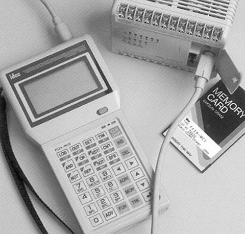
Figure 2-4 - Programmer Connected to a Shoebox PLC (IDEC Corporation)
2-5. System Block Diagram 系统模块图
A Programmable Controller is a
specialized computer.
可编程控制器是一种专用计算机。
Since it is a computer, it has all the basic component parts that any other
computer has; a Central Processing Unit, Memory, Input Interfacing and Output
Interfacing.
由于它是一台计算机,它具有任何其他计算机所具有的所有基本部件:中央处理器、存储器、输入接口和输出接口。
A typical programmable controller block diagram is shown in Figure 2-5.
典型的可编程控制器框图如图2-5所示。
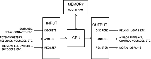
Figure 2-5
- Programmable Controller Block
Diagram
The Central Processing Unit (CPU) is
the control portion of the PLC.
中央处理器(CPU)是PLC的控制部分。
It interprets the program commands retrieved from memory and acts on those
commands.
它解释从内存中检索到的程序命令,并对这些命令执行操作。
In present day PLC's this unit is a microprocessor based system.
在当今的PLC中,该单元是一个基于微处理器的系统。
The CPU is housed in the processor module of modularized systems.
CPU安装在模块化系统的处理器模块中。
Memory in the system is generally of two types; ROM and RAM.
系统中的存储器通常有两种类型:ROM和RAM。
The ROM memory contains the program information that allows the CPU to
interpret and act on the Ladder Logic program stored in the RAM memory.
ROM存储器包含允许CPU解释存储在RAM存储器中的梯形逻辑程序并对其执行的程序信息。
RAM memory is generally kept alive with an on-board battery so that ladder
programming is not lost when the system power is removed.
RAM存储器通常通过板载电池保持活动状态,因此当系统断电时梯形图编程不会丢失。
This battery can be a standard dry cell or rechargeable nickel-cadmium type.
该电池可以是标准干电池,也可以是可充电镍镉电池。
Newer PLC units are now available with Electrically Erasable Programmable Read
Only Memory (EEPROM) which does not require a battery.
较新的PLC单元现已提供不需要电池的电可擦除可编程只读存储器(EEPROM)。
Memory is also housed in the processor module in modular systems.
存储器也容纳在模块化系统中的处理器模块中。
Input units can be any of several different types depending on input signals
expected as described above.
根据如上所述预期的输入信号,输入单元可以是几种不同类型中的任何一种。
The input section can accept discrete or analog signals of various voltage and
current levels.
输入部分可以接受各种电压和电流电平的离散或模拟信号。
Present day controllers offer discrete signal inputs of both AC and DC voltages
from TTL to 250 VDC and from 5 to 250 VAC.
目前的控制器提供从TTL到250 VDC和从5到250 VAC的交流和直流电压的离散信号输入。
Analog input units can accept input levels such as ±10 VDC, ±5 VDC and 4-20
ma.
模拟输入单元可以接受±10 VDC、±5 VDC和4-20 mA等输入电平。
current loop values.
当前循环值。
Discrete input units present each input to the CPU as a single 1 or 0 while
analog input units contain analog to digital conversion circuitry and present
the input voltage to the CPU as binary number normalized to the maximum count
available from the unit.
离散输入单元将每个输入呈现为单个1或0,而模拟输入单元包含模数转换电路,并且将输入电压呈现为归一化为该单元可用最大计数的二进制数。
The number of bits representing the input voltage or current depends upon the
resolution of the unit.
表示输入电压或电流的位数取决于单元的分辨率。
This number generally contains a defined number of magnitude bits and a sign
bit.
该数字通常包含定义数量的幅值比特和符号比特。
Register input units present the word input to the CPU as it is received
(Binary or BCD).
寄存器输入单元在接收字输入时将其呈现给CPU(二进制或BCD)。
Output units operate much the same as the input units with the exception that
the unit is either sinking (supplying a ground) or sourcing (providing a
voltage) discrete voltages or sourcing analog voltage or current.
输出单元的操作与输入单元基本相同,不同之处在于该单元要么下沉(提供接地),要么提供(提供电压)离散电压,或者提供模拟电压或电流。
These output signals are presented as directed by the CPU.
这些输出信号按照CPU的指示呈现。
The output circuit of discrete units can be transistors for TTL and higher DC
voltage or Triacs for AC voltage outputs.
分立单元的输出电路可以是用于TTL和更高直流电压的晶体管或用于交流电压输出的可控硅。
For higher current applications and situations where a physical contact closure
is required, mechanical relay contacts are available.
对于电流较高的应用和需要物理触点闭合的情况,可提供机械继电器触点。
These higher currents, however, are generally limited to about 2-3 amperes.
然而,这些较高的电流通常被限制在大约2-3安培。
The analog output units have internal circuitry which performs the digital to
analog conversion and generates the variable voltage or current output.
模拟输出单元具有执行数模转换并产生可变电压或电流输出的内部电路。
2-6. ... - Update - Solve the Ladder - Update - ...
When power is applied to a
programmable logic controller, the PLC’s operation
consists of two steps: (1) update inputs and outputs and (2) solve the ladder.
当可编程控制器通电时,PLC的操作包括两个步骤:(1)更新输入输出和(2)求解梯形图。
This may seem like a very simplistic approach to something that has to be more
complicated but there truly are only these two steps.
对于必须更复杂的事情,这似乎是一种非常简单的方法,但实际上只有这两个步骤。
If these two steps are thoroughly understood, writing and modifying programs
and getting the most from the device is much easier to accomplish.
如果彻底理解了这两个步骤,编写和修改程序并最大限度地利用设备就容易得多了。
With this understanding, the things that can be undertaken are then up to the
imagination of the programmer.
有了这样的理解,接下来可以做的事情就取决于程序员的想象力了。
You will notice that the “update - solve the ladder” sequence begins
after startup.
您将注意到“更新-求解阶梯”序列在启动后开始。
The actual startup sequence includes some operations transparent to the user or
programmer that occur before actual PLC operation on the user program begins.
实际启动序列包括一些对用户或程序员透明的操作,这些操作发生在用户程序上的实际PLC操作开始之前。
During this startup there may be extensive diagnostic checks performed by the
processor on things like memory, I/O devices, communication with other devices
(if present) and program integrity.
在此启动期间,处理器可能会对内存、I/O设备、与其他设备的通信(如果存在)和程序完整性等内容执行广泛的诊断检查。
In sophisticated modular systems, the processor is able to identify the various
module types, their location in the system and address.
在复杂的模块化系统中,处理器能够识别各种模块类型、它们在系统中的位置和地址。
This type of system analysis and testing generally occurs during startup before
actual program execution.
这种类型的系统分析和测试通常发生在实际程序执行之前的启动期间。
2-7. Update 更新
The first thing the PLC does when it begins to function is update I/O. This
means that all discrete input states are recorded from the input unit and all
discrete states to be output are transferred to the output unit.
PLC开始工作的第一件事是更新I/O,这意味着所有离散的输入状态都从输入单元记录下来,所有要输出的离散状态都转移到输出单元。
Register data generally has specific addresses associated with it for both
input and output data referred to as input and output registers.
对于称为输入和输出寄存器的输入和输出数据,寄存器数据通常具有与其相关联的特定地址。
These registers are available to the input and output modules requiring them and
are updated with the discrete data.
这些寄存器可供需要它们的输入和输出模块使用,并使用离散数据进行更新。
Since this is input/output updating, it is referred to as I/O Update.
由于这是输入/输出更新,因此称为I/O更新。
The updating of discrete input and output information is accomplished with the
use of input and output image registers set aside in the PLC memory.
离散输入和输出信息的更新是通过使用PLC存储器中预留的输入和输出图像寄存器来完成的。
Each discrete input point has associated with it one bit of an input image
register.
每个离散输入点具有与其相关联的输入图像寄存器的一位。
Likewise, each discrete output point has one bit of an output image register
associated with it.
同样,每个离散输出点具有与其相关联的输出图像寄存器的一位。
When I/O updating occurs, each input point that is ON at that time will cause a
1 to be set at the bit address associated with that particular input.
当I/O更新发生时,此时打开的每个输入点将导致在与该特定输入相关联的位地址处设置1。
If the input is off, a 0 will be set into the bit address.
如果输入为OFF,则位地址将设置为0。
Memory in today's PLC's is generally configured in 16 bit words.
今天的PLC中的存储器通常配置为16位字。
This means that one word of memory can store the states of 16 discrete input
points.
这意味着存储器的一个字可以存储16个离散输入点的状态。
Therefore, there may be a number of words of memory set aside as the input and
output image registers.
因此,可能有多个存储器字留作输入和输出图像寄存器。
At I/O update, the status of the input image register is set according to the
state of all discrete inputs and the status of the output image register is
transferred to the output unit.
在I/O更新时,根据所有离散输入的状态设置输入图像寄存器的状态,并将输出图像寄存器的状态传送到输出单元。
This transfer of information typically only occurs at I/O update.
这种信息传输通常仅在I/O更新时发生。
It may be forced to occur at other times in PLC's which have an Immediate I/O
Update command.
它可能被强制在具有立即I/O更新命令的PLC中的其他时间发生。
This command will force the PLC to update the I/O at other times although this
would be a special case.
此命令将强制PLC在其他时间更新I/O,尽管这将是特殊情况。
One major item of concern about the first output update is the initial state of
outputs.
关于第一次输出更新的一个主要问题是输出的初始状态。
This is a concern because their may be outputs that if initially turned on
could create a safety hazard, particularly in a system which is controlling
heavy mechanical devices capable of causing bodily harm to operators.
这是一个令人担忧的问题,因为它们可能是输出,如果最初打开,可能会产生安全危险,特别是在控制能够对操作员造成身体伤害的重型机械设备的系统中。
In some systems, all outputs may need to be initially set to their off state to
insure the safety of the system.
在某些系统中,可能需要将所有输出初始设置为关闭状态,以确保系统安全。
However, there may be systems that require outputs to initially be set up in a
specific way, some on and some off.
但是,可能有一些系统需要以特定的方式初始设置输出,有些是开,有些是关。
This could take the form of a predetermined setup or could be a requirement
that the outputs remain in the state immediately before power-down.
这可以采取预定设置的形式,或者可以要求输出保持在紧接断电之前的状态。
More recent systems have provisions for both setup options and even a
combination of the two.
较新的系统同时提供了设置选项,甚至提供了这两个选项的组合。
This is a prime concern of the engineer and programmer and must be defined as
the system is being developed to insure the safety of personnel that operate
and maintain the equipment.
这是工程师和程序员最关心的问题,必须在开发系统以确保操作和维护设备的人员的安全时加以定义。
Safety as related to system and program development will be discussed in a
later chapter.
与系统和程序开发相关的安全性将在后面的章节中讨论。
2-8. Solve the Ladder 解梯形图
After the I/O update has been
accomplished, the PLC begins executing the commands programmed into it.
I/O更新完成后,PLC开始执行编程到其中的命令。
These commands are typically referred to as the ladder diagram.
这些命令通常称为梯形图。
The ladder diagram is basically a representation of the program steps using
relay contacts and coils.
梯形图基本上是使用继电器触点和线圈表示程序步骤。
The ladder is drawn with contacts to the left side of the sheet and coils to
the right.
梯子绘制时,触点位于板材的左侧,线圈位于右侧。
This is a holdover from the time when control systems were relay based.
这是控制系统基于继电器时的遗留问题。
This type of diagram was used for the electrical schematic of those systems.
这些系统的电气原理图使用了这种类型的图。
A sample ladder diagram is shown in Figure 2-6.
梯形图示例如图2-6所示。
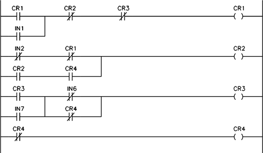
Figure 2-6 - Sample Ladder
Diagram
The symbols used in Figure 2-6 may be
foreign at this point, so a short explanation will be necessary.
图2-6中使用的符号在这一点上可能是外来的,所以有必要做一个简短的解释。
The symbols at the right of the ladder diagram labeled CR1, CR2, CR3 and CR4
and are circular in shape are the software coils of the relays.
梯形图右侧标有CR1、CR2、CR3和CR4的圆形符号是继电器的软件线圈。
The symbols at the left which look like capacitors, some with diagonal lines through
them, are the contacts associated with the coils.
左边的符号看起来像电容器,有些符号中间有对角线,它们是与线圈相关的触点。
The symbols that look like capacitors without the diagonal lines through them
are normally open contacts.
看起来像电容器的符号没有通过它们的对角线,它们是常开触点。
These are analogous to a switch that is normally off.
它们类似于通常处于关闭状态的开关。
When the switch is turned on, the contact closes.
当开关接通时,触点闭合。
The contact symbols at the left that look like capacitors with diagonal lines
through them are normally closed contacts.
左边的触点符号看起来像电容器,中间有对角线,它们是常闭触点。
A normally closed contact is equivalent to a switch that is normally turned on.
常闭触点相当于常开的开关。
It will turn off when the switch is actuated.
当开关被启动时,它将关闭。
As can be seen in Figure 2-6, contact and coil position is as described above.
如图2-6所示,触点和线圈的位置如上所述。
Also, one can see the reason for the term ladder diagram if the rungs of a
stepladder are visualized.
此外,如果把梯子的梯级形象化,就可以看出梯形图这个术语的由来。
In fact, each complete line of the diagram is referred to as one rung of logic.
事实上,图中的每一条完整的线都被称为一级逻辑。
The actual interpretation of the diagram will also be discussed later although
some explanation is required here.
图的实际解释也将在后面讨论,尽管这里需要一些解释。
The contact configuration on the left side of each rung can be visualized as
switches and the coils on the right as lights.
每个横档左侧的触点配置可以显示为开关,右侧的线圈显示为灯。
If the switches are turned on and off in the proper configuration, the light to
the right will illuminate.
如果开关在正确的配置中打开和关闭,则右侧的指示灯将亮起。
The PLC executes this program from left to right and top to bottom, in that
order.
PLC按照从左到右和从上到下的顺序执行此程序。
It first looks at the switch (contact) configuration to determine if current
can be passed to the light (coil).
它首先查看开关(触点)配置,以确定电流是否可以传递到灯(线圈)。
The data for this decision comes from the output and input image registers.
此决策的数据来自输出和输入图像寄存器。
If current can be passed, the light (coil) will then be turned on.
如果电流可以通过,灯(线圈)就会打开。
If not, the light (coil) will be turned off.
如果没有,灯(线圈)将关闭。
This is recorded in the output image register.
这记录在输出图像寄存器中。
Once the PLC has looked at the left side of the rung it ignores the left side
of the rung until the next time it solves that particular rung.
一旦PLC查看了横档的左侧,它就会忽略横档的左侧,直到下一次求解该特定横档。
Once the light (coil) has been either turned on or off it will remain in that
state until the next time the PLC solves that particular rung.
一旦灯(线圈)打开或关闭,它将保持该状态,直到PLC下一次解决该特定横档。
After solving a rung, the PLC moves on to solve the next rung in the same
manner and so forth until the entire ladder has been executed and solved.
在求解一个梯级之后,PLC继续以相同的方式求解下一个梯级,依此类推,直到整个阶梯执行完毕并求解完毕。
One rule that is different from general electrical operation is the direction
of current flow in the rung.
与一般电气操作不同的一条规则是横档中电流的流向。
In a ladder logic, rung current can only flow from left to right and up and
down; never from right to left.
在梯形逻辑中,横档电流只能从左向右和上下流动,而不能从右向左流动。
As an example, in the ladder shown in Figure 2-7, coil CR1 will energize if any
of the following conditions exist:
例如,在图2-7所示的梯子中,如果存在以下任何情况,线圈CR1将通电:
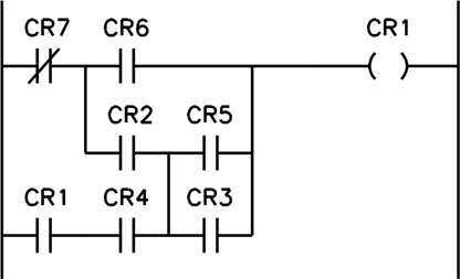
Figure 2-7
Illustration of allowed current flow in ladder rung
1.
CR7 is off, CR6 is on.
2.
CR7 is off, CR2 is on, CR5 is on.
3.
CR7 is off, CR2 is on, CR3 is on. 4. CR1 is on, CR4 is on, CR3 is on.
5. CR1 is on, CR4 is on, CR5 is on.
You will notice that the current flow
in the circuit in each of the cases listed above is from left to right and up
and down.
您会注意到,在上面列出的每种情况下,电路中的电流是从左到右、向上和向下的。
CR1 will not energize in the case listed below:
在下列情况下,CR1将不会通电:
CR1 is on, CR4 is on, CR2 is on, CR6 is on, CR5 is off, CR3 is off, CR7
is on.
This is because current would have to
flow from right to left through the CR2 contact.
这是因为电流必须从右向左流过CR2触点。
This is not allowed in ladder logic even though current could flow in this
direction if we were to build it with real relays.
这在梯形逻辑中是不允许的,即使如果我们用真正的继电器建造它,电流可能会沿着这个方向流动。
Remember, we are working in the software world not the hardware world.
请记住,我们是在软件世界工作,而不是在硬件世界工作。
To review, after the I/O update, the PLC moves to the first rung of ladder
logic.
回顾一下,在I/O更新之后,PLC移动到梯形逻辑的第一级。
It solves the contact configuration to determine if the coil is to be energized
or de-energized.
它求解触点配置以确定线圈是通电还是断电。
It then energizes or de-energizes the coil.
然后它给线圈通电或断电。
After this is accomplished, it moves to the left side of the next rung and
repeats the procedure.
完成此操作后,它将移动到下一个梯级的左侧,并重复该过程。
This continues until all rungs have been solved.
这将一直持续到所有梯级都已解决。
When this procedure is complete with all rungs solved and all coils in the
ladder set up according to the solution of each rung, the PLC proceeds to the
next step of it's sequence, the I/O update.
当此过程完成时,所有梯级都已解决,并且阶梯中的所有线圈都根据每个梯级的解进行设置,PLC将继续其序列的下一步,即I/O更新。
At I/O update, the states of all coils which are designated as outputs are
transferred from the output image register to the output unit and the states of
all inputs are transferred to the input image register.
在I/O更新时,指定为输出的所有线圈的状态从输出图像寄存器传输到输出单元,并且所有输入的状态传输到输入图像寄存器。
Note that any input changes that occur during the solution of the ladder are
ignored because they are only recorded at I/O update time.
请注意,阶梯求解过程中发生的任何输入更改都会被忽略,因为它们只在I/O更新时记录。
The state of each coil is recorded to the output image register as each rung is
solved.
在求解每个横档时,每个线圈的状态被记录到输出图像寄存器。
However, these states are not transferred to the output unit until I/O update
time.
但是,这些状态在I/O更新时间之前不会传输到输出单元。
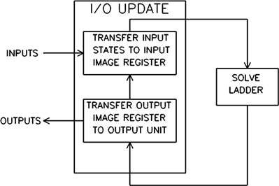
Figure 2-8 - Scan Cycle
This procedure of I/O update and
solving the ladder diagram and I/O update is referred to as scanning and is
represented in Figure 2-8.
这个I/O更新和求解梯形图和I/O更新的过程称为扫描,如图2-8所示。
The period between one I/O update and the next is referred to as one Scan.
一次I/O更新和下一次I/O更新之间的时间段称为一次扫描。
The amount of time it takes the PLC to get from one I/O update to the next is
referred to as Scan Time.
PLC从一次I/O更新到下一次更新所需的时间称为扫描时间。
Scan time is typically measured in milliseconds and is related to the speed of
the CPU and the length of the ladder diagram that has to be solved.
扫描时间通常以毫秒为单位测量,并且与CPU的速度和必须求解的梯形图的长度有关。
The slower the processor or the longer the ladder diagram, the longer the scan
time of the system.
处理器速度越慢或梯形图越长,系统的扫描时间就越长。
The speed at which a PLC scans memory is referred to as Scan Rate.
PLC扫描存储器的速度称为扫描速率。
Scan rate units are usually listed in msec/K of memory being utilized for the
program.
扫描速率单位通常以程序使用的内存的毫秒/K为单位列出。
As an example, if a particular PLC has a rated scan rate of 8 msec/K and the
program occupies 6K of memory, it will take the PLC 48 msec to complete one
scan of the program.
例如,如果特定PLC的额定扫描速率为8毫秒/K,并且该程序占用6K的存储器,则该PLC将花费48毫秒来完成该程序的一次扫描。
2-9. Summary 总结
Before a study of PLC programming can
begin, it is important to gain a fundamental understanding of the various types
of PLCs available, the advantages and disadvantages of each, and the way in
which a PLC executes a program.
在开始学习PLC编程之前,重要的是对现有的各种PLC类型、每种PLC的优缺点以及PLC执行程序的方式有一个基本的了解。
The open frame, shoebox, and modular PLCs are each best suited to specific
types of applications based on the environmental conditions, number of inputs
and outputs, ease of expansion, and method of entering and monitoring the
program.
根据环境条件、输入和输出数量、扩展的易用性以及进入和监控程序的方法,开放式框架、鞋盒和模块化PLC均最适合特定类型的应用。
Additionally, programming requires a prior knowledge of the manner in which a
PLC receives input information, executes a program, and sends output
information.
此外,编程需要事先了解PLC接收输入信息、执行程序和发送输出信息的方式。
With this information, we are now prepared to begin a study of PLC programming
techniques.
有了这些信息,我们现在准备开始学习PLC编程技术。